

Blake Courter
@bcourter.bsky.social
Incubating engineering software startups. Applying SDFs to design and manufacturing problems by generalizing them to fields with unit gradient magnitude (UGFs).
https://www.blakecourter.com/
https://www.blakecourter.com/
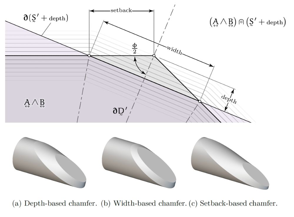
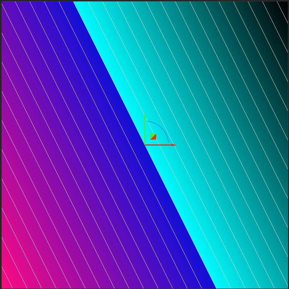
Instead, we can create a surface at an arbitrary angle Θ to the normalized S or D fields via S * cos(Θ) + D * sin(Θ) .
Algebraic geometers call this family a "pencil".
With such an angled face at any angle and offset, we can describe any surface from the edge in "Hesse normal form".
(9/n)
Algebraic geometers call this family a "pencil".
With such an angled face at any angle and offset, we can describe any surface from the edge in "Hesse normal form".
(9/n)
November 25, 2024 at 3:35 AM
Instead, we can create a surface at an arbitrary angle Θ to the normalized S or D fields via S * cos(Θ) + D * sin(Θ) .
Algebraic geometers call this family a "pencil".
With such an angled face at any angle and offset, we can describe any surface from the edge in "Hesse normal form".
(9/n)
Algebraic geometers call this family a "pencil".
With such an angled face at any angle and offset, we can describe any surface from the edge in "Hesse normal form".
(9/n)
To convert to a constant width or a constant setback chamfer, one simply does some trig on the triangle to figure out what the inset should be based on the angle between the gradients of A and B.
(7/n)
(7/n)
November 25, 2024 at 3:27 AM
To convert to a constant width or a constant setback chamfer, one simply does some trig on the triangle to figure out what the inset should be based on the angle between the gradients of A and B.
(7/n)
(7/n)
To get a chamfer, we just need to offset our normalized A + B field inward and intersect again. This result produces a constant inset chamfer, where the width increases with dihedral angle between faces.
(6/n)
(6/n)

November 25, 2024 at 3:14 AM
To get a chamfer, we just need to offset our normalized A + B field inward and intersect again. This result produces a constant inset chamfer, where the width increases with dihedral angle between faces.
(6/n)
(6/n)
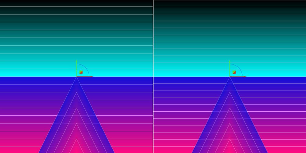
Here is A + B with A ∩ B overlaid above. Looks okay at first glance, but notice (left) that the spacing between the contours is wider than our original fields. It's gradient magnitude is not unity, but we can normalize the field by dividing by that magnitude (right).
(It's a bit subtle.)
(5/n)
(It's a bit subtle.)
(5/n)
November 25, 2024 at 3:12 AM
Here is A + B with A ∩ B overlaid above. Looks okay at first glance, but notice (left) that the spacing between the contours is wider than our original fields. It's gradient magnitude is not unity, but we can normalize the field by dividing by that magnitude (right).
(It's a bit subtle.)
(5/n)
(It's a bit subtle.)
(5/n)
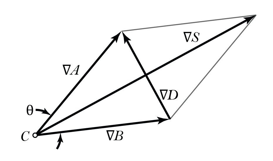
UGFs are more special than general implicits because their gradient has unit magnitude. The sum and difference of two unit vectors are perpendicular, as seen in the diagonals of the rhombus of the vectors.
Defining:
S = A + B
D = A - B
Interactive version: www.shadertoy.com/view/dd2cWy
(4/n)
Defining:
S = A + B
D = A - B
Interactive version: www.shadertoy.com/view/dd2cWy
(4/n)
November 25, 2024 at 3:07 AM
UGFs are more special than general implicits because their gradient has unit magnitude. The sum and difference of two unit vectors are perpendicular, as seen in the diagonals of the rhombus of the vectors.
Defining:
S = A + B
D = A - B
Interactive version: www.shadertoy.com/view/dd2cWy
(4/n)
Defining:
S = A + B
D = A - B
Interactive version: www.shadertoy.com/view/dd2cWy
(4/n)
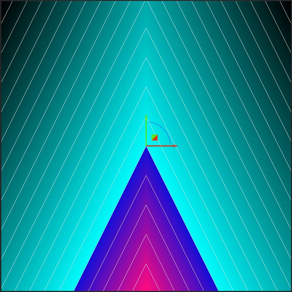
We will can intersect these together by taking the max of the fields. (Our sign convention is that inside is negative.)
This corner, A ∩ B, is what we want to chamfer. Note that this result is not an SDF, but a UGF, because the field extending up from the corner is sharp.
(3/n)
This corner, A ∩ B, is what we want to chamfer. Note that this result is not an SDF, but a UGF, because the field extending up from the corner is sharp.
(3/n)
November 25, 2024 at 3:03 AM
We will can intersect these together by taking the max of the fields. (Our sign convention is that inside is negative.)
This corner, A ∩ B, is what we want to chamfer. Note that this result is not an SDF, but a UGF, because the field extending up from the corner is sharp.
(3/n)
This corner, A ∩ B, is what we want to chamfer. Note that this result is not an SDF, but a UGF, because the field extending up from the corner is sharp.
(3/n)
Let's work in 2D so we can visualize the field. We will take two planes represented as signed distance fields (SDFs), and let's call those fields "A" and "B".
Here's A. B will just be it's mirror image across the vertical axis:
(2/n)
Here's A. B will just be it's mirror image across the vertical axis:
(2/n)
November 25, 2024 at 3:02 AM
Let's work in 2D so we can visualize the field. We will take two planes represented as signed distance fields (SDFs), and let's call those fields "A" and "B".
Here's A. B will just be it's mirror image across the vertical axis:
(2/n)
Here's A. B will just be it's mirror image across the vertical axis:
(2/n)
Let's take a look at another application where UGFs are the appropriate setting: chamfers, in particular the constant-width flavor.
(UGFs are a generalization of SDFs considering fields with unit gradient magnitude. www.blakecourter.com/2023/05/18/f...)
Images are from #nTop .
(1/n)
(UGFs are a generalization of SDFs considering fields with unit gradient magnitude. www.blakecourter.com/2023/05/18/f...)
Images are from #nTop .
(1/n)

November 25, 2024 at 3:01 AM
Let's take a look at another application where UGFs are the appropriate setting: chamfers, in particular the constant-width flavor.
(UGFs are a generalization of SDFs considering fields with unit gradient magnitude. www.blakecourter.com/2023/05/18/f...)
Images are from #nTop .
(1/n)
(UGFs are a generalization of SDFs considering fields with unit gradient magnitude. www.blakecourter.com/2023/05/18/f...)
Images are from #nTop .
(1/n)
One of the main applications of the two body field in generative mechanical applications is to create mappings for lattices, ribs, and other conformal structures.
(6/n)
(6/n)

November 22, 2024 at 2:47 AM
One of the main applications of the two body field in generative mechanical applications is to create mappings for lattices, ribs, and other conformal structures.
(6/n)
(6/n)
When A and B are UGFs (have unit gradient magnitude), A - B and A + B are orthogonal.
While interesting, I have not found this aspect of the approach useful for conformally mapping lattices.
(5/n)
While interesting, I have not found this aspect of the approach useful for conformally mapping lattices.
(5/n)

November 22, 2024 at 2:44 AM
When A and B are UGFs (have unit gradient magnitude), A - B and A + B are orthogonal.
While interesting, I have not found this aspect of the approach useful for conformally mapping lattices.
(5/n)
While interesting, I have not found this aspect of the approach useful for conformally mapping lattices.
(5/n)
Looking at the fields with some 1D examples, it's clear how the quotient of the difference and sum normalize to the [-1, 1] range from body to body.
From the blog post here: www.blakecourter.com/2023/07/01/t...
(4/n)
From the blog post here: www.blakecourter.com/2023/07/01/t...
(4/n)

November 22, 2024 at 2:39 AM
Looking at the fields with some 1D examples, it's clear how the quotient of the difference and sum normalize to the [-1, 1] range from body to body.
From the blog post here: www.blakecourter.com/2023/07/01/t...
(4/n)
From the blog post here: www.blakecourter.com/2023/07/01/t...
(4/n)
Meanwhile, their difference A - B represents a midsurface, with order flipping its direction. One might divide by two to normalize to a more distance-like field.
Midsurfacing can be a tricky operation on explicit geometry like meshes and is near unheard of on B-reps.
(3/n)
Midsurfacing can be a tricky operation on explicit geometry like meshes and is near unheard of on B-reps.
(3/n)

November 22, 2024 at 2:37 AM
Meanwhile, their difference A - B represents a midsurface, with order flipping its direction. One might divide by two to normalize to a more distance-like field.
Midsurfacing can be a tricky operation on explicit geometry like meshes and is near unheard of on B-reps.
(3/n)
Midsurfacing can be a tricky operation on explicit geometry like meshes and is near unheard of on B-reps.
(3/n)
Let's break down what's happening. A + B represents the local clearance or interference. If A and B are SDFs, inf(A + B) represents the Hausdorff distance or max interference between them.
Interactive ShaderToy here: www.shadertoy.com/view/DssczX
(2/n)
Interactive ShaderToy here: www.shadertoy.com/view/DssczX
(2/n)

November 22, 2024 at 2:34 AM
Let's break down what's happening. A + B represents the local clearance or interference. If A and B are SDFs, inf(A + B) represents the Hausdorff distance or max interference between them.
Interactive ShaderToy here: www.shadertoy.com/view/DssczX
(2/n)
Interactive ShaderToy here: www.shadertoy.com/view/DssczX
(2/n)
Let's take a look at one of the most useful tricks in applied implicit modeling, a trick I like to call the "two body field". For two SDFs or UGFs A and B, let's define the two body field Ξ = (A - B) / (A + B) .
It creates a field that linearly interpolates from -1 at A to +1 at B.
(1/n)
It creates a field that linearly interpolates from -1 at A to +1 at B.
(1/n)

November 22, 2024 at 2:26 AM
Let's take a look at one of the most useful tricks in applied implicit modeling, a trick I like to call the "two body field". For two SDFs or UGFs A and B, let's define the two body field Ξ = (A - B) / (A + B) .
It creates a field that linearly interpolates from -1 at A to +1 at B.
(1/n)
It creates a field that linearly interpolates from -1 at A to +1 at B.
(1/n)
For some more details, although still a bit cursory, here are some posts:
www.blakecourter.com/2023/05/05/w...
www.blakecourter.com/2023/05/18/f...
There's also a big crazy diagram and the beginning of an API for high-level implicit modeling.
Next time: another UGF application.
(5/n) n = 5.
www.blakecourter.com/2023/05/05/w...
www.blakecourter.com/2023/05/18/f...
There's also a big crazy diagram and the beginning of an API for high-level implicit modeling.
Next time: another UGF application.
(5/n) n = 5.

November 20, 2024 at 2:30 AM
For some more details, although still a bit cursory, here are some posts:
www.blakecourter.com/2023/05/05/w...
www.blakecourter.com/2023/05/18/f...
There's also a big crazy diagram and the beginning of an API for high-level implicit modeling.
Next time: another UGF application.
(5/n) n = 5.
www.blakecourter.com/2023/05/05/w...
www.blakecourter.com/2023/05/18/f...
There's also a big crazy diagram and the beginning of an API for high-level implicit modeling.
Next time: another UGF application.
(5/n) n = 5.
UGFs form a more expressive language for CAD than SDFs. For example, different UGF booleans on the cube enable this blend transition, which would be different algorithms in a Brep modeling kernel.
(3/n)
(3/n)

November 20, 2024 at 2:16 AM
UGFs form a more expressive language for CAD than SDFs. For example, different UGF booleans on the cube enable this blend transition, which would be different algorithms in a Brep modeling kernel.
(3/n)
(3/n)
There are some properties, like the boundary map, that are unique to SDFs. However, there are other properties, like offset being well-behaved, that they share.
SDFs always refer to a set, but UGFs need not have any boundary or inside components. UGFs facilitate intermediate operations.
(2/n)
SDFs always refer to a set, but UGFs need not have any boundary or inside components. UGFs facilitate intermediate operations.
(2/n)

November 20, 2024 at 2:13 AM
There are some properties, like the boundary map, that are unique to SDFs. However, there are other properties, like offset being well-behaved, that they share.
SDFs always refer to a set, but UGFs need not have any boundary or inside components. UGFs facilitate intermediate operations.
(2/n)
SDFs always refer to a set, but UGFs need not have any boundary or inside components. UGFs facilitate intermediate operations.
(2/n)
Greetings everyone! Here's a quick intro to my main project: I study Unit Gradient Fields (UGFs), which are a generalization of Signed Distance Fields (SDFs).
Common operations on SDFs like offset and booleans fail to result in SDFs. These operations, with care, do result in UGFs!
(1/n)
Common operations on SDFs like offset and booleans fail to result in SDFs. These operations, with care, do result in UGFs!
(1/n)

November 20, 2024 at 2:07 AM
Greetings everyone! Here's a quick intro to my main project: I study Unit Gradient Fields (UGFs), which are a generalization of Signed Distance Fields (SDFs).
Common operations on SDFs like offset and booleans fail to result in SDFs. These operations, with care, do result in UGFs!
(1/n)
Common operations on SDFs like offset and booleans fail to result in SDFs. These operations, with care, do result in UGFs!
(1/n)
To visualize, it helps to trim to the SDF via an intersect with the unsigned distance field to the medial axis:
This process works as long as you keep your boolean results SDF-like, but you don't have to normalize the medial distance field, as it isn't used in the running computation.
(9/n)
This process works as long as you keep your boolean results SDF-like, but you don't have to normalize the medial distance field, as it isn't used in the running computation.
(9/n)

November 19, 2024 at 2:42 AM
To visualize, it helps to trim to the SDF via an intersect with the unsigned distance field to the medial axis:
This process works as long as you keep your boolean results SDF-like, but you don't have to normalize the medial distance field, as it isn't used in the running computation.
(9/n)
This process works as long as you keep your boolean results SDF-like, but you don't have to normalize the medial distance field, as it isn't used in the running computation.
(9/n)
Here's |M_A∩B'| - δ .
For the union, there are no new internal medial axes, so it's just like the step for M_Old before.
To track the cut loci (medial axis of the set complement), just invert and swap operations.
So with ever boolean, you can keep track of both sets of discontinuities!
(8/n)
For the union, there are no new internal medial axes, so it's just like the step for M_Old before.
To track the cut loci (medial axis of the set complement), just invert and swap operations.
So with ever boolean, you can keep track of both sets of discontinuities!
(8/n)

November 19, 2024 at 2:38 AM
Here's |M_A∩B'| - δ .
For the union, there are no new internal medial axes, so it's just like the step for M_Old before.
To track the cut loci (medial axis of the set complement), just invert and swap operations.
So with ever boolean, you can keep track of both sets of discontinuities!
(8/n)
For the union, there are no new internal medial axes, so it's just like the step for M_Old before.
To track the cut loci (medial axis of the set complement), just invert and swap operations.
So with ever boolean, you can keep track of both sets of discontinuities!
(8/n)
Defining gradient (Sampson) normalization as ⧚-⧛, Here's a first order normalized distance field to the medial axis: M_A∩B' = |M_Old| > |⧚M_New⧛| ? M_Old : ⧚M_New⧛
(7/n)
(7/n)

November 19, 2024 at 2:35 AM
Defining gradient (Sampson) normalization as ⧚-⧛, Here's a first order normalized distance field to the medial axis: M_A∩B' = |M_Old| > |⧚M_New⧛| ? M_Old : ⧚M_New⧛
(7/n)
(7/n)
(Actually 5 was unnormalized.)
To combine them, M_A∩B = |M_Old| > |M_New| ? M_Old : M_New. (Remember, it is only correct inside the shape.)
(6/n)
To combine them, M_A∩B = |M_Old| > |M_New| ? M_Old : M_New. (Remember, it is only correct inside the shape.)
(6/n)

November 19, 2024 at 2:35 AM
(Actually 5 was unnormalized.)
To combine them, M_A∩B = |M_Old| > |M_New| ? M_Old : M_New. (Remember, it is only correct inside the shape.)
(6/n)
To combine them, M_A∩B = |M_Old| > |M_New| ? M_Old : M_New. (Remember, it is only correct inside the shape.)
(6/n)
Let's also define M_New = A - B. As A and B are SDFs, A - B , is their midsurface. It is not an SDF, but it could be normalized, which we'll approximate by dividing by the gradient magnitude.
(5/n)
(5/n)

November 19, 2024 at 2:33 AM
Let's also define M_New = A - B. As A and B are SDFs, A - B , is their midsurface. It is not an SDF, but it could be normalized, which we'll approximate by dividing by the gradient magnitude.
(5/n)
(5/n)
Our intersection is made of three regions: A wins, B wins, and an optional blending region. The blending region doesn't affect the medial axis and is outside the part, so let's ignore it.
We get MA when A wins and MB when B wins. So let's call M_Old = A > B ? MA : MB ....
(4/n)
We get MA when A wins and MB when B wins. So let's call M_Old = A > B ? MA : MB ....
(4/n)

November 19, 2024 at 2:32 AM
Our intersection is made of three regions: A wins, B wins, and an optional blending region. The blending region doesn't affect the medial axis and is outside the part, so let's ignore it.
We get MA when A wins and MB when B wins. So let's call M_Old = A > B ? MA : MB ....
(4/n)
We get MA when A wins and MB when B wins. So let's call M_Old = A > B ? MA : MB ....
(4/n)
We start with SDFs A and B with known (optionally signed) SDFs to their medial axes MA and MB. Let's call A a circle and B an infinite slab |y| - k. MA is the DF to the circle's center point and MB is y. Here's an approximate SDF of A ∩ B:
(2/n)
(2/n)

November 19, 2024 at 2:26 AM
We start with SDFs A and B with known (optionally signed) SDFs to their medial axes MA and MB. Let's call A a circle and B an infinite slab |y| - k. MA is the DF to the circle's center point and MB is y. Here's an approximate SDF of A ∩ B:
(2/n)
(2/n)