


Dr. Obbs
@dr-obbs.bsky.social
Engineer, PhD Fluid Mechanics, Motorsport Tech Creator, Co-host for Braking Bias Podcast, ✝️, Proud husband and dad, Turkish/American lived in Germany and UK, opinions & snark my own.
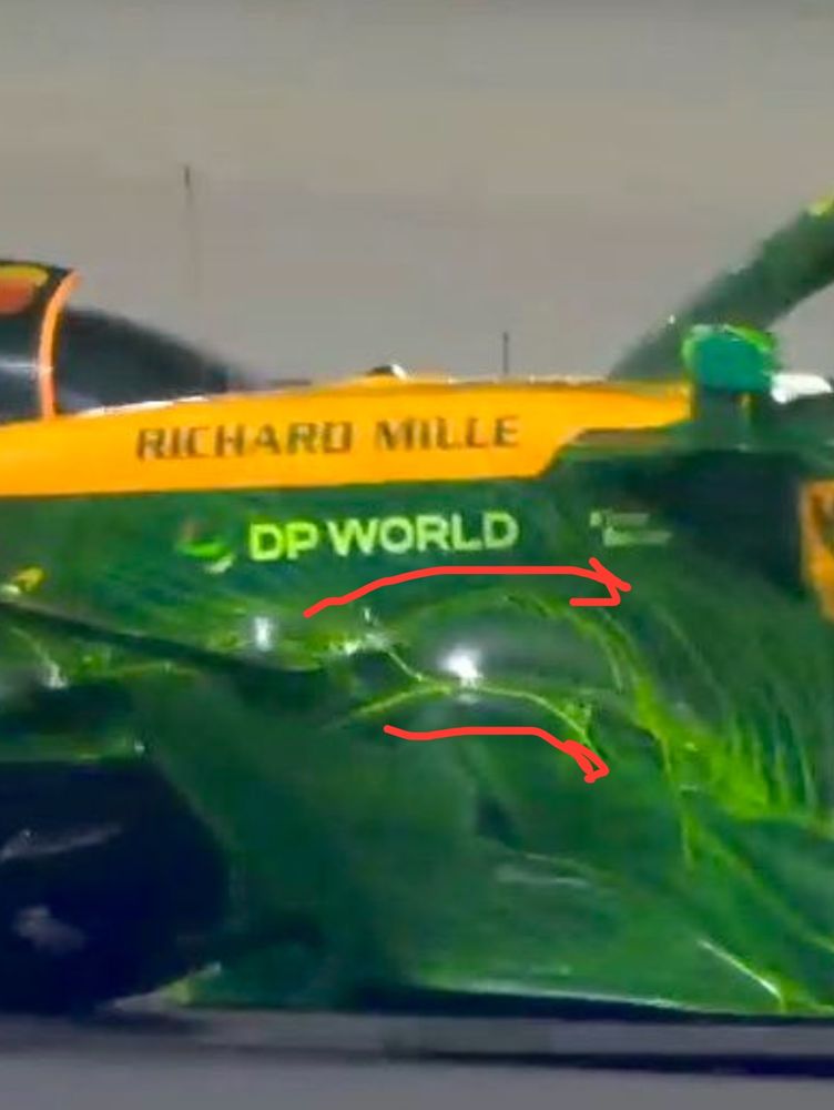
Vortices are hard to see from Flow Vis, but I believe that the below image is showing some swirl or rotation at this exact location of the training edge of the upwashing junction. Theory supported? 🤓
Flow Vis image from Floorent Gooden on instagram.
Flow Vis image from Floorent Gooden on instagram.


June 30, 2025 at 2:55 PM
Vortices are hard to see from Flow Vis, but I believe that the below image is showing some swirl or rotation at this exact location of the training edge of the upwashing junction. Theory supported? 🤓
Flow Vis image from Floorent Gooden on instagram.
Flow Vis image from Floorent Gooden on instagram.
In my analysis of the McLaren MCL39 FSUS junction update, I had questioned if the new aggressive upwashing junctions might shed a small vortex that could re-energize the slow moving boundary layer along the nose.
June 30, 2025 at 2:55 PM
In my analysis of the McLaren MCL39 FSUS junction update, I had questioned if the new aggressive upwashing junctions might shed a small vortex that could re-energize the slow moving boundary layer along the nose.
.. This larger merged vortex stays outboard of the front Tyre and downwashes air onto the outboard Tyre jet which can help to suppress and dissipate it quicker reducing any negative influence it may have on your floor edge downstream.

June 13, 2025 at 8:41 PM
.. This larger merged vortex stays outboard of the front Tyre and downwashes air onto the outboard Tyre jet which can help to suppress and dissipate it quicker reducing any negative influence it may have on your floor edge downstream.
McLaren introduced a new front wing with some interesting little end element winglets. IMO, these aren’t really wings generating much load. They are more vortex generators shedding counter-clockwise small vortices that all co-rotate and merge downstream…cont

June 13, 2025 at 8:41 PM
McLaren introduced a new front wing with some interesting little end element winglets. IMO, these aren’t really wings generating much load. They are more vortex generators shedding counter-clockwise small vortices that all co-rotate and merge downstream…cont
Heck of a glow up for McLaren from 2022 to present on the front brakes. From a liability to an advantage. That’s just great engineering folks!


April 10, 2025 at 9:04 PM
Heck of a glow up for McLaren from 2022 to present on the front brakes. From a liability to an advantage. That’s just great engineering folks!
I think that these vortices will detach and be counter rotating with bulk outwash btwn them. The benefit of this could be creating more outwash using the side pod for the upper front tyre wake. It's a really interesting design, and I wonder if more teams could be looking at this option as well.

March 27, 2025 at 4:40 PM
I think that these vortices will detach and be counter rotating with bulk outwash btwn them. The benefit of this could be creating more outwash using the side pod for the upper front tyre wake. It's a really interesting design, and I wonder if more teams could be looking at this option as well.
Obv, having the CFD would help, but I think that the inlet pressure is > than the local pressure on either side. The upper edge will have the downwash from the shark inlet, so ⬇️ P. The bottom edge could just be marginally less, even though you will have some forward undercut pressure built up here.
March 27, 2025 at 4:40 PM
Obv, having the CFD would help, but I think that the inlet pressure is > than the local pressure on either side. The upper edge will have the downwash from the shark inlet, so ⬇️ P. The bottom edge could just be marginally less, even though you will have some forward undercut pressure built up here.
Both of the extended upper and lower edges look like vortex shedding edges. So it's safe to say that there is some rotation along these edges. But how to resolve the direction?
March 27, 2025 at 4:40 PM
Both of the extended upper and lower edges look like vortex shedding edges. So it's safe to say that there is some rotation along these edges. But how to resolve the direction?
Been thinking about this new Sauber Side Pod intake since I first saw it. Pretty cool little design. Here is what I THINK is happening. 🧵
March 27, 2025 at 4:40 PM
Been thinking about this new Sauber Side Pod intake since I first saw it. Pretty cool little design. Here is what I THINK is happening. 🧵
The space between the rads and the exhaust headers is where the depression is in the sidepod, with the headers forming the “tail” of the tadpod. This allows Merc to maximize the downwash of the sidepod transition into the rear coke, and slim the shape of outboard sidepod volume maximizing undercut..

March 13, 2025 at 6:44 PM
The space between the rads and the exhaust headers is where the depression is in the sidepod, with the headers forming the “tail” of the tadpod. This allows Merc to maximize the downwash of the sidepod transition into the rear coke, and slim the shape of outboard sidepod volume maximizing undercut..
Some are calling the new Mercedes W16 side pod the “tadpod” as it looks like the shape of a tadpole. Pitlane shots from Albert Park now shows how Mercedes did this. You can see the “belly” of the tadpole shape where the rads are located and stacked.
March 13, 2025 at 6:44 PM
Some are calling the new Mercedes W16 side pod the “tadpod” as it looks like the shape of a tadpole. Pitlane shots from Albert Park now shows how Mercedes did this. You can see the “belly” of the tadpole shape where the rads are located and stacked.
For the blue arrow, we can also see a bit of the boundary layer as the slower moving air upstream of the suspension junction doesn't have as much paint. The influence of the solid body creates an upstream pressure build up that helps to deflect some of the air around it. @xavigazquez.bsky.social

March 8, 2025 at 9:26 AM
For the blue arrow, we can also see a bit of the boundary layer as the slower moving air upstream of the suspension junction doesn't have as much paint. The influence of the solid body creates an upstream pressure build up that helps to deflect some of the air around it. @xavigazquez.bsky.social
LOVE FLOW VIS!! RB21 here...
Red arrow shows that the aero neutral suspension arms aren't as down washing as some might expect. This shows an upwards trajectory after the rear leg from the flow coming off the front wing. We do see some downward deflection from the flow UNDER the trailing arm.
Red arrow shows that the aero neutral suspension arms aren't as down washing as some might expect. This shows an upwards trajectory after the rear leg from the flow coming off the front wing. We do see some downward deflection from the flow UNDER the trailing arm.
March 8, 2025 at 9:26 AM
LOVE FLOW VIS!! RB21 here...
Red arrow shows that the aero neutral suspension arms aren't as down washing as some might expect. This shows an upwards trajectory after the rear leg from the flow coming off the front wing. We do see some downward deflection from the flow UNDER the trailing arm.
Red arrow shows that the aero neutral suspension arms aren't as down washing as some might expect. This shows an upwards trajectory after the rear leg from the flow coming off the front wing. We do see some downward deflection from the flow UNDER the trailing arm.
So to see these two regions of what looks like high shear, and a clear line of flow pattern difference just sparked my curiosity. Not saying this is 100% mini-DRS, nor do I know for sure what it is. But even speaking with other aero’s it’s very curious.

March 5, 2025 at 12:08 AM
So to see these two regions of what looks like high shear, and a clear line of flow pattern difference just sparked my curiosity. Not saying this is 100% mini-DRS, nor do I know for sure what it is. But even speaking with other aero’s it’s very curious.
When I first saw the flow vis posted by @xaviimages I knew something was a bit off. It’s not typical that you see these types of patterns. Even with the new cut end wings (see MCL from 2023) the junction from where the DRS and end piece meet is usually uniform and neat…
March 5, 2025 at 12:08 AM
When I first saw the flow vis posted by @xaviimages I knew something was a bit off. It’s not typical that you see these types of patterns. Even with the new cut end wings (see MCL from 2023) the junction from where the DRS and end piece meet is usually uniform and neat…
Hell of a week last week huh? 😂😂

March 3, 2025 at 3:31 AM
Hell of a week last week huh? 😂😂
A good look at how the Mercedes W16 forward floor is working. Pretty standard solutions today using a small forward edge gurney, and integrated curl with VG's on the edge wing. Always a good thing to explain for some that may not have seen this before.

February 27, 2025 at 4:24 PM
A good look at how the Mercedes W16 forward floor is working. Pretty standard solutions today using a small forward edge gurney, and integrated curl with VG's on the edge wing. Always a good thing to explain for some that may not have seen this before.
Really interesting look here at the RB21 G-Line. There seems to be a slight bulge maybe in the floor (Blue) which funnels the floor edge wing inflow into a particular position. Possibly some influence from the forward curl? The mechanics here are fascinating.

February 27, 2025 at 4:23 PM
Really interesting look here at the RB21 G-Line. There seems to be a slight bulge maybe in the floor (Blue) which funnels the floor edge wing inflow into a particular position. Possibly some influence from the forward curl? The mechanics here are fascinating.
Then along the g-line we can see the outwash of air pulled down into the floor edge wing. More than likely spinning up some structures that load up the floor edge and clean up the diffuser. (Lower arrows)

February 26, 2025 at 6:21 PM
Then along the g-line we can see the outwash of air pulled down into the floor edge wing. More than likely spinning up some structures that load up the floor edge and clean up the diffuser. (Lower arrows)
Then here we can see the air from alongside the center cooling box migrating down into the water slide where low pressure suction is building as it ramps down. (Top arrow)
February 26, 2025 at 6:21 PM
Then here we can see the air from alongside the center cooling box migrating down into the water slide where low pressure suction is building as it ramps down. (Top arrow)
and the higher pressure at the SP inlet and under wing then pushing this air down onto the floor top deck and into the undercut. It’s clear as day.
February 26, 2025 at 6:21 PM
and the higher pressure at the SP inlet and under wing then pushing this air down onto the floor top deck and into the undercut. It’s clear as day.
A good photo from Mateusz M on X where we can draw a few observations from this. Firstly, we can see the influence of the floor leading edge in helping to upwash some of the inboard air from the nose and FW,
February 26, 2025 at 6:21 PM
A good photo from Mateusz M on X where we can draw a few observations from this. Firstly, we can see the influence of the floor leading edge in helping to upwash some of the inboard air from the nose and FW,
Williams gave us a nice shot of this with some of their flow vis during testing in 2024. You can see the additional challenge of the push rod front suspension with the quite complex junction geometry. This is the cool stuff we have to look forward to in testing next week!!

February 23, 2025 at 5:34 PM
Williams gave us a nice shot of this with some of their flow vis during testing in 2024. You can see the additional challenge of the push rod front suspension with the quite complex junction geometry. This is the cool stuff we have to look forward to in testing next week!!
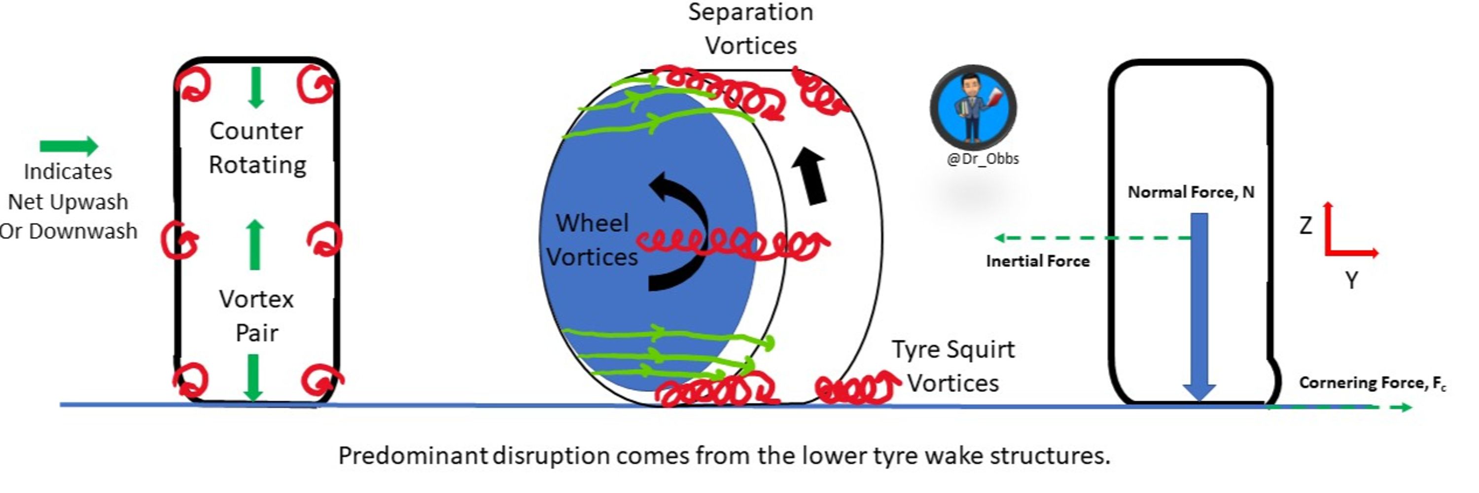
Nice graphic showing the types of vortices that can be formed at the junction of two surfaces. Easy to see this as an example of the a-arm fairing junction with the monocoque. Without junction fairings (gaiters or flexis) the losses could be disruptive to distress aero elements

February 23, 2025 at 5:34 PM
Nice graphic showing the types of vortices that can be formed at the junction of two surfaces. Easy to see this as an example of the a-arm fairing junction with the monocoque. Without junction fairings (gaiters or flexis) the losses could be disruptive to distress aero elements
"Yep that's me.... you re probably wondering how I ended up in this situation.. "

February 18, 2025 at 8:47 PM
"Yep that's me.... you re probably wondering how I ended up in this situation.. "